Flat, uniform zones
The main decision is usually matching the regulator setting to the selected emitter pressure and verifying it with a gauge.


Views: 0 Author: Site Editor Publish Time: 2026-11-21 Origin: Site


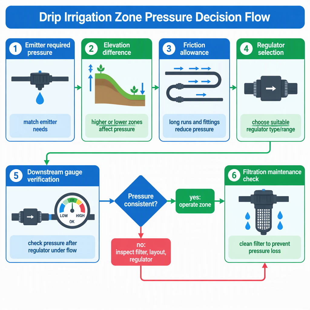
Set each drip irrigation zone from the emitter operating pressure required for that zone, then verify it with a downstream gauge under operating flow. Pressure-compensating emitters can reduce flow variation, but they do not remove the need to account for elevation, layout loss, filtration and maintenance.
The right pressure reference is the selected emitter’s required operating pressure at the zone, not the maximum pressure a pump can supply.
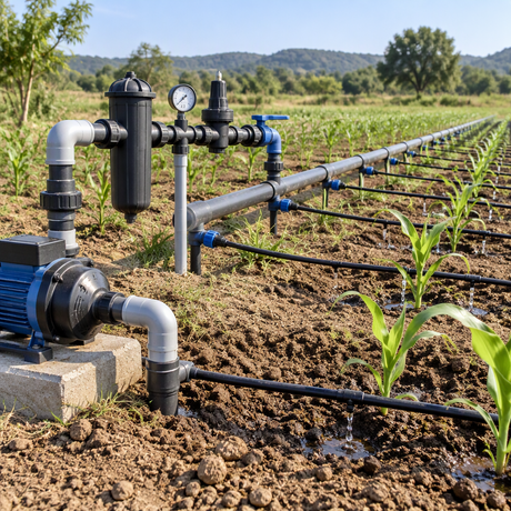
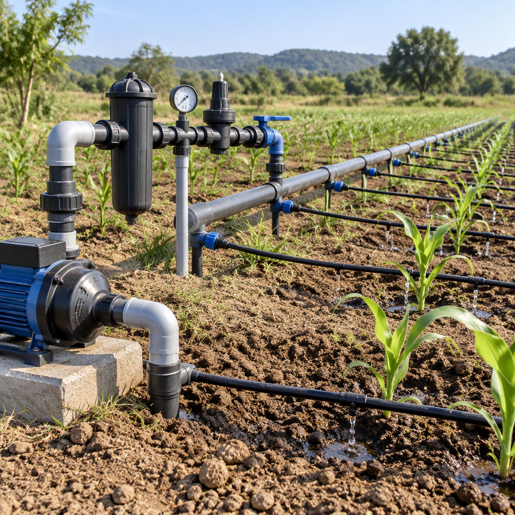
A drip system normally combines a pump unit, control head, main and submain lines, laterals and emitters; the pump supplies pressure, while the control head can control discharge and pressure and include filtration.
For procurement, this means the zone specification should name the emitter type, the manufacturer’s recommended pressure, the expected zone flow and the measuring point where pressure will be checked.
The FAO drip irrigation chapter describes the system components that make pressure control a zone-level design task rather than a pump-only choice.
A zone pressure window should allow for the emitter’s required pressure, elevation difference and layout effects before the regulator is selected.
| Input to confirm | Why it matters for pressure regulation | Buyer action |
|---|---|---|
| Emitter operating pressure | Emitters must operate at a specific pressure, so the zone setting starts with the emitter requirement. | Request the pressure range or design pressure for the selected emitter or dripline. |
| Elevation difference | Elevation can change emitter discharge along laterals, and FAO notes that laterals are normally laid along contours to reduce this effect. | Provide high and low points for every zone, not only the pump location. |
| Uphill adjustment example | University Extension gives a windbreak-system example in which pressure is increased by 5 psi for every 10 feet of rise above the manifold when using pressure-compensating emitters. | Use this only as a contextual example; base the final setting on the selected emitter data and the project hydraulic calculation. |
Do not treat an elevation example as a universal rule. It shows the calculation logic, while the final pressure window still depends on the emitter, field elevation profile, pipe sizing, zone flow and commissioning measurement.
Pressure-compensating emitters help reduce flow fluctuation, but regulators and gauges are still needed when zone pressure must be controlled and verified.
| Option | Useful when | Limit to check before buying |
|---|---|---|
| Non-compensating emitters with regulator | The zone can be kept near the emitter’s required operating pressure. | More sensitive to pressure variation from slope and long laterals. |
| Pressure-compensating emitters | The project needs reduced flow variation compared with non-compensating emitters. | They are not 100 percent effective, so pressure still needs to be checked. |
| Pressure-compensating emitters plus zone regulation | Useful where varying pressure must be managed while still respecting the emitter’s compensation mechanism. | The compensation diaphragm and flow channels can be affected by clogging or deterioration, especially with marginal water. |
The AGRIS record on pressure-compensating emitter failure behavior describes pressure compensation through an internal diaphragm and notes failure risks related to clogging and diaphragm performance.
Set pressure with the zone running, then verify it at a downstream gauge rather than relying only on a static upstream reading.
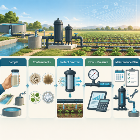
Filtration and water-quality control protect pressure regulation because clogged emitters can distort the relationship between pressure and discharge.
FAO identifies emitter blockage as a main drip-irrigation problem because emitter waterways are small; algae, fertilizer deposits and precipitating chemicals such as calcium and iron can contribute to blockage.
Pressure is set for emitter performance, while discharge, spacing and layout must still match the soil wetting pattern and crop arrangement.
The main decision is usually matching the regulator setting to the selected emitter pressure and verifying it with a gauge.
Elevation differences can change discharge, so lateral routing along contours and pressure checks at representative points become more important.
FAO notes that wetting patterns depend on discharge and soil type, so pressure selection should be coordinated with emitter flow, spacing and irrigation scheduling.
A useful RFQ should define the zone, water source and control components clearly enough for the supplier to size pressure regulation around real operating conditions.
| If the RFQ says only... | Ask for... |
|---|---|
| “Drip irrigation pressure regulation” | Zone flow, emitter pressure range, elevation profile and filter requirement. |
| “Pressure-compensating emitter” | The operating range and whether separate zone pressure regulation is still required. |
| “High-slope field” | A hydraulic calculation and commissioning gauge plan for the high and low points. |
There is no single safe psi setting for every drip zone because the target pressure depends on the selected emitter and field conditions.
University Extension gives a 15–25 psi range in a windbreak drip-irrigation context and advises following the manufacturer-recommended design pressure unless elevation differences require adjustment.
Pressure-compensating emitters reduce major flow fluctuation compared with non-compensating emitters, but they are not a substitute for checking the pressure range and the zone’s hydraulic conditions.
DFSHOU can be considered as a supplier context for irrigation equipment categories, while the zone pressure setting should still be specified from emitter data and project hydraulics.
The first-party DFSHOU website presents DFSHOU as a custom irrigation equipment manufacturer and supplier in China and lists categories including drip irrigation pipe, irrigation filters, irrigation solenoid valves, drip emitters and irrigation sprinklers.
When requesting a quotation, separate the general design package from the supplier conversation: provide the hydraulic inputs, ask for compatible components, and request product-specific pressure ranges, filtration guidance and commissioning limits in writing.
Set each zone by working backward from emitter pressure, then forward through elevation, losses, filtration and field verification.
These answers address the most common buying and commissioning questions for drip irrigation pressure regulation.
Set it to the selected emitter’s recommended operating pressure after allowing for elevation and system losses; do not use pump pressure as the final zone setting.
No. The pump provides system pressure, while the control head and zone components control discharge, filtration and pressure delivered to the laterals.
Often yes. They reduce flow fluctuation, but they are not perfectly effective and must still operate within the selected product’s pressure limits.
Slope changes the pressure available at emitters by elevation, so layout along contours and pressure checks at representative high and low points are important.
Emitter waterways are small, and blockage from biological growth, fertilizer deposits or precipitating minerals can change discharge even when gauge pressure appears acceptable.
Send emitter pressure requirements, zone flow, elevation differences, line lengths, water-quality information, filtration needs and planned gauge locations.
Soil type does not replace the emitter pressure requirement, but it affects wetting pattern decisions, so pressure, discharge, spacing and scheduling should be coordinated.
No. Published examples are context-specific; the final value should follow the selected emitter data and the project’s elevation and hydraulic calculation.