English


Views: 0 Author: Site Editor Publish Time: 2026-10-19 Origin: Site


Extending drip lines too far results in uneven water distribution. You will see dry spots at the end of the run. This leads to potential crop or plant failure. Guessing lateral limits wastes money on materials. It requires costly system redesigns later. Many growers try stretching irrigation runs past mathematical capacities. This ignores crucial hydraulic realities. When pressure drops too low, the last emitters barely drip.
You cannot just stretch irrigation runs indefinitely. You must define the hard hydraulic limits of drip tubing. This article provides evidence-based solutions for scaling irrigation systems effectively. We explore pressure thresholds, friction rules, and structural design upgrades. You will learn how to evaluate tubing sizes correctly. We will teach you how to prevent dead ends in your layout. Accurate planning saves you from seasonal crop losses.
The absolute maximum drip irrigation line length depends strictly on tubing diameter, emitter flow rate, and incoming pressure.
As a hard industry rule of thumb, 1/2-inch tubing should not exceed 200 feet or 200 Gallons Per Hour (GPH).
Drip line friction loss acts as an invisible barrier; every foot of tubing and every emitter reduces available pressure.
Overcoming length limitations requires evaluating pressure-compensating (PC) emitters, upgrading to larger mainline manifolds, or splitting zones.
You must determine the exact maximum drip irrigation line length before purchasing materials. Tubing diameter strictly dictates water volume limits. Planners often ignore these mathematical boundaries. We see failing systems constantly because of this specific mistake. Let us look at the famous "200/200" rule. This represents a primary industry standard for half-inch tubing. The rule states half-inch laterals should never exceed 200 feet. They also should never push more than 200 Gallons Per Hour (GPH) of total flow. Exceeding either metric causes massive pressure drops. Your plants will suffer from severe underwatering.
Micro-tubing presents even stricter engineering constraints. Quarter-inch tubing hits a very hard 30-foot limit. Some designers push it to 33 feet, but risk increases drastically. Pushing past 30 feet creates zero-pressure dead ends. Friction overcomes flow entirely. Water simply will not drip from the final emitters. You should use quarter-inch tubing strictly for short feeder lines directing water to individual pots.
Commercial agricultural applications require massive water volumes. They rely on larger pipes to overcome distance and feed thousands of crops. Stepping up to three-quarter-inch tubing changes the math favorably. It allows lateral runs up to 480 feet. Upgrading to one-inch tubing supports lateral runs up to 1,000 feet. Optimal conditions must exist for these maximums. The terrain must remain relatively flat, and the incoming supply must provide sufficient static pressure.
You must verify exact internal diameters before buying anything. Check the manufacturer specification sheet thoroughly. The label "half-inch tubing" varies wildly between different brands. Some budget brands use a .520 internal diameter (ID). Professional agricultural brands often use a .600 ID. This small physical difference completely changes hydraulic capacity. A .600 ID pipe carries significantly more water than a .520 ID pipe. You must size your connectors to match this ID perfectly.
Tubing Size (Nominal) | Maximum Run Length | Maximum Flow Capacity (GPH) | Primary Application Use Case |
|---|---|---|---|
1/4-inch (Micro) | 30 feet | 30 GPH | Container plants, short feeder branches |
1/2-inch (Standard) | 200 feet | 200 GPH | Backyard gardens, small row crops |
3/4-inch (Commercial) | 480 feet | 480 GPH | Medium farms, large orchard rows |
1-inch (Agricultural) | 1,000 feet | 1,000 GPH | Massive agricultural fields, mainlines |
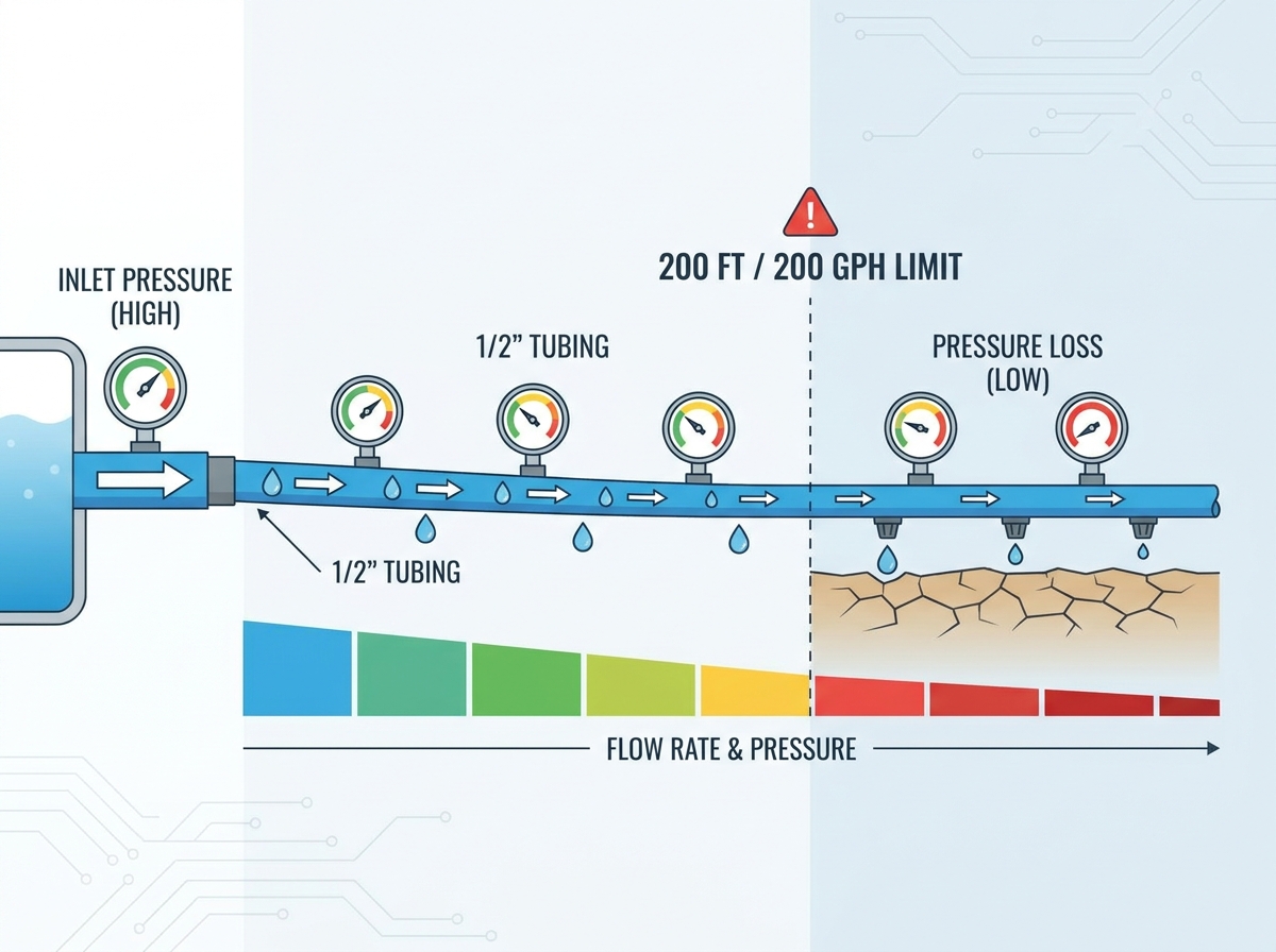
Water rubbing against interior pipe walls slows down. This creates intense drip line friction loss. It decreases water pressure sequentially down the line. Every single foot of tubing steals a tiny bit of kinetic energy. The longer the run, the weaker the push. Friction acts as an invisible barrier to your system layout. You cannot bypass it.
Flow rate and friction velocity share a strict inverse relationship. Pushing higher GPH through narrow tubing exponentially increases friction. High water volume forced into tiny spaces causes severe turbulence. Pressure plummets rapidly when you force too much water through a small opening. Fluid dynamics rules dictate that doubling the water volume quadruples the friction penalty.
Elevation changes directly impact head pressure. You must account for gravity in your field design. Topography plays a massive role in system success or failure.
Uphill runs: You lose roughly 0.43 PSI per foot of elevation gain. Pushing water up a steep ten-foot hill destroys 4.3 PSI. You must calculate this penalty immediately to ensure the top emitters work.
Downhill runs: You gain pressure moving downhill. Gravity acts as an invisible pump. This risks blowing out delicate end fittings. It also creates uneven high-flow spots at the bottom of the slope.
A properly designed system has clear success criteria. You must maintain minimum pressure levels everywhere. Target 10 to 15 PSI at the very last emitter on the line. If you hit this mark, your layout works perfectly. Pressure gauges help verify this success in the field. Planners often test the end of the line before burying any pipe.
Many environmental factors shrink your maximum drip irrigation lateral length. You cannot base designs purely on pipe diameter. You must account for actual demand variables. Plant spacing changes everything about your hydraulic math. Never assume a 200-foot pipe can always handle 200 feet of dense planting.
Emitter Spacing Density: Tighter spacing increases total flow demand dramatically. Six-inch spacing drains pressure much faster than eighteen-inch spacing. This drastically reduces your viable length of the lateral. You hit the maximum GPH limit much faster when plants sit close together.
High-Flow vs. Low-Flow Emitters: Emitter output dictates your ultimate reach. Using 2.0 GPH emitters forces very short tubing runs. One hundred plants demand 200 GPH instantly, maxing out a half-inch line. Using 0.5 GPH emitters allows much longer stretches. You can water four hundred plants on that exact same line. Lower flow preserves pressure longer.
Fittings and Connections: Couplers do not just join pipes seamlessly. Tees, elbows, and splices introduce intense micro-turbulence. They act as artificial friction points. Every single fitting reduces overall run length slightly. Keep layouts straight whenever possible to conserve energy.
Common Mistake: Growers often snake a single line back and forth around trees. This introduces dozens of sharp elbows. The severe turbulence kills pressure long before you reach the mathematical distance limit. Always opt for straight laterals branching off a central pipe.
You will eventually hit length limitations in large gardens. Basic half-inch lines cannot water vast fields alone. System upgrades become highly necessary. Let us explore the best architectural fixes for scaling up your agricultural layout.
First, consider investing in Pressure Compensating (PC) emitters. They contain tiny internal diaphragms to regulate flow. They respond dynamically to incoming water pressure. The first and last plants receive the exact same water volume. You just need to meet the minimum PSI requirement across the line. They excel on long runs and sloped terrain. They guarantee uniform crop yield. However, they possess a higher upfront cost than standard turbulent-flow emitters.
Next, look at manifold and sub-main architecture. End-feeding a long lateral is rarely optimal. Pushing water from one far edge guarantees uneven pressure distribution. Instead, run a large PVC or poly mainline to the center of the planting area. Branch shorter laterals off the middle. This center-feeding strategy effectively doubles your watering area safely. A single 200-foot line becomes two 100-foot lines extending in opposite directions.
Finally, evaluate zone splitting. Flow demand sometimes surpasses the available supply completely. A single run might exceed 400 feet, demanding 600 GPH from a spigot that only yields 300 GPH. Splitting the massive area into mechanically timed zones is smart. Multi-valve setups offer the most reliable architectural fix. You water zone one entirely, then shut it off. Then you water zone two. This prevents overtaxing your pump.
Upgrade Category | Primary Mechanism | Best Use Case Scenario | Implementation Difficulty |
|---|---|---|---|
PC Emitters | Internal diaphragms equalize water output | Sloped terrain and exceptionally long straight rows | Low (Swap out parts) |
Center-Feeding Manifolds | Splits lateral distance strictly in half | Large, wide fields needing symmetrical watering | Medium (Requires PVC plumbing) |
Zone Splitting | Divides total GPH demand across multiple timers | Systems where total demand exceeds water source capacity | High (Requires wiring and valves) |
Growers often rely on bad advice from internet forums. They make extremely costly design mistakes. The "looping" myth remains incredibly common among beginners. Many believe connecting the end of a long line back to the beginning doubles pressure. It absolutely does not double your pressure. It only slightly mitigates friction loss. It mostly masks core flow-rate deficits temporarily. If you lack total GPH, looping fails completely.
Avoid mixing emitter types on extreme runs. Never combine PC and non-PC emitters on the same long lateral. This causes unpredictable watering depths. PC emitters restrict flow to maintain balance. Non-PC emitters dump water based on raw line pressure. Some plants will drown while others dehydrate. Standardize your emitter technology per zone for predictable growth.
Ignoring filtration on long runs ruins systems quickly. Maximized lines have very low pressure at the extreme end. They cannot flush out debris properly during purge cycles. Algae and mineral deposits accumulate fast. High-mesh Y-filters become completely mandatory here. They prevent severe sediment clogging. We recommend installing a 120-mesh filter on any line exceeding 100 feet.
Shortlist your next steps carefully before buying plastic tubing.
Audit your current GPH demand first by counting every single plant.
Measure your static water pressure accurately at the main spigot.
Size your tubing accordingly based on strict math.
Purchase materials only after plotting the final layout on paper.
Pushing irrigation laterals past mathematical limits guarantees system underperformance. Physics will always win against poorly designed plumbing. You must scale watering systems carefully to protect your plants. Ignoring hydraulic realities wastes vital resources and ruins harvests.
Calculate total GPH demand precisely before building.
Factor in expected friction loss accurately across the yard.
Step up pipe diameter immediately for longer agricultural runs.
Use PC emitters to scale safely across uneven terrain.
Break large fields into smaller, mechanically timed watering zones.
Direct your attention to proper planning tools next. Consult a pipe sizing calculator to verify your exact numbers. Read a detailed pressure regulator selection guide. Seek a professional system design consultation if you remain unsure about your layout dynamics.
A: No. Industry standards dictate the strict 200/200 rule. Limit half-inch tubing to 200 feet in length. Limit total flow to 200 GPH. Exceeding these metrics causes severe pressure drops. Your last emitters will not release enough water to keep plants alive.
A: No, looping does not magically increase static pressure. It simply equalizes flow across the line. This slightly masks friction loss on weak setups. If your total GPH demand exceeds your supply, looping will not fix the underlying deficit.
A: You need extreme upgrades for this distance. Use large diameter mainlines like 1-inch poly or PVC. Center-feed your layout to create stepped-down laterals. You must also install pressure-compensating (PC) emitters to ensure uniform watering over such vast stretches.
A: Your system will show clear failure symptoms quickly. You will see weeping emitters near the end. Soil will remain completely dry at the furthest points. Overworking the line also places extreme strain on your pumps and valves, leading to premature wear.