English


Views: 0 Author: Site Editor Publish Time: 2026-10-29 Origin: Site


Applying a one-size-fits-all approach to irrigation inevitably leads to disaster. It creates dry spots, waterlogged roots, and wasted resources across your fields. Water moves through the ground based entirely on particle size and capillary action. Ignoring this fundamental physics guarantees poor system performance and severely stressed crops.
You need a properly configured setup to ensure healthy plant growth. A correctly spaced drip system creates a continuous, overlapping subterranean wetted band along the plant row. It accomplishes this efficiently without causing surface runoff or deep percolation. Achieving this balance requires matching your hardware to your local ground conditions.
This guide gives you evidence-based spacing and flow rate configurations. We base these recommendations on agricultural extension standards and proven commercial irrigation principles. You will learn how to evaluate soil texture accurately and calculate hydraulic limits. Ultimately, this knowledge helps you procure the exact tubing and emitters required for your specific site.
Sandy Soil: Requires close drip emitter spacing (12 inches or less) and higher flow rates (1.0 to 2.0 GPH) due to rapid vertical drainage.
Clay Soil: Requires wider drip emitter spacing for clay soil (18 to 24+ inches) and low flow rates (0.5 GPH) to prevent surface pooling and runoff.
Loamy Soil: Offers the most flexibility, typically requiring 12 to 18-inch spacing and moderate flow rates (0.5 to 1.0 GPH).
System Pairing: Emitter spacing must always be calculated alongside emitter flow rate (Gallons Per Hour) and soil infiltration rate to ensure system scalability and pressure stability.
Understanding water movement requires examining the "wetting bulb." When water exits an emitter, gravity immediately pulls it downward. Simultaneously, capillary forces pull moisture horizontally through tiny pore spaces. These two opposing forces create a distinct moisture profile beneath the surface. You must design your system around this specific geometric shape.
Soil texture heavily dictates this physical interaction. Large particles characterize sandy environments. These coarse textures provide minimal capillary resistance. Consequently, water travels straight down very quickly. Conversely, microscopic particles define clay environments. They bind tightly together and resist rapid absorption. This high density forces water to spread outward horizontally before it finally sinks.
We use a standard evaluation framework to measure design success. You must follow these criteria to ensure a viable layout:
Observe the individual wetting bulbs beneath adjacent emitters.
Measure the maximum horizontal radius of each bulb.
Ensure the edges of adjacent bulbs overlap by roughly 20% to 30%.
This precise overlap forms a continuous moisture strip for root systems. Proper drip emitter spacing ensures plant roots can always access water easily.
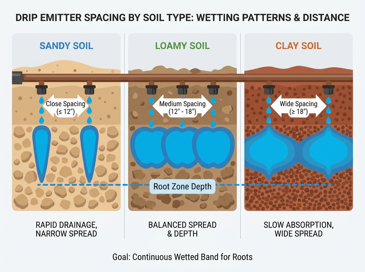
When irrigating sand, the subterranean wetting pattern forms a narrow, deep "carrot" shape. Gravity completely dominates the water movement here. Moisture sinks rapidly into the earth before it can spread horizontally across the surface.
You must use tight spacing specifications to compensate. Keep emitters at 10 to 12 inches maximum. Anything wider leaves dangerous dry gaps between the moisture zones. These gaps easily strand young roots and stunt overall crop development. Calculating the correct drip emitter spacing for sandy soil actively prevents these barren zones.
Flow rate requirements also differ significantly. You generally need 1.0 to 2.0 Gallons Per Hour (GPH). Water must enter the ground very quickly. A high flow rate forces horizontal spread before gravity pulls the moisture below the active root zone.
There are distinct implementation risks to monitor:
Nutrient leaching becomes a severe hazard if run times extend too long. Fast-draining water carries expensive liquid fertilizers far away from the roots.
You must use shorter, more frequent watering cycles. Industry professionals call this pulse irrigation.
A standard schedule might require four separate 15-minute intervals rather than one continuous hour.
Clay dictates a completely different irrigation approach. Its wetting pattern forms a wide, shallow "onion" shape. Water spreads outward aggressively across the dense surface due to strong capillary resistance.
Spacing specifications must reflect this broad horizontal movement. You typically need 18 to 24 inches between watering points. Placing emitters too closely oversaturates the dense matrix. This internal flooding physically displaces essential oxygen. Carefully planning your drip emitter spacing for clay soil prevents plant suffocation.
Flow rate requirements drop drastically in these conditions. You must use 0.4 to 0.5 GPH emitters. Clay has a stubbornly low infiltration rate. It often absorbs less than 0.25 inches of water per hour. High-flow emitters easily overwhelm this slow absorption limit. They cause immediate surface pooling, runoff, and severe evaporation loss.
Watch out for several implementation risks:
Compaction and surface sealing occur if water pools repeatedly over time. A sealed crust permanently reduces future moisture infiltration.
Poor drainage creates a remarkably high risk of fungal root rot.
You must factor extended drying times into your automation controller. Always program sufficient resting intervals between watering days.
Loam provides the most forgiving agricultural environment. Its wetting pattern forms a uniform, rounded "apple" shape. Capillary action and gravity balance out almost perfectly here. This balance supports aggressive root expansion.
Spacing specifications offer comfortable design flexibility. You generally need 12 to 18 inches between emitters. You can easily adjust this baseline based on specific crop density. Use tight spacing for densely seeded vegetable rows. Conversely, use wider placement for established perennials and large orchards.
Flow rate requirements fall right in the middle spectrum. Aim for 0.5 to 1.0 GPH. This moderate application prevents pooling while keeping deep roots adequately fed.
However, there are still implementation risks to monitor. True loam can vary widely across a single property. Site-specific "jar tests" or manual ribbon tests should always be conducted. Perform these checks before making bulk tubing purchases. A ribbon test involves squeezing moist earth in your hand. If it holds a shape easily, it leans toward clay-loam. If it crumbles quickly, it leans toward sandy-loam. You can adjust your final hardware setup accordingly.
Evaluating your system requires more than just texture matching. You must carefully balance hydraulics and physical hardware limits to ensure longevity.
First, consider Pressure Compensating (PC) vs. Non-PC emitters. Friction loss is notably higher over long irrigation runs. This resistance increases exponentially for tightly spaced emitters. PC emitters are entirely non-negotiable for runs over 50 feet. They are also mandatory on uneven agricultural terrain. They ensure uniform output regardless of elevation drops or distance from the water source.
System capacity limits dictate your maximum zone size. Narrower placement means more emitters per foot. Consider this basic calculation logic. If you run 100 feet of tubing containing 12-inch spacing at 1.0 GPH, you create 100 GPH of total demand. Ensure your water source and main zone valves can support this cumulative flow rate. Exceeding this limit causes massive pressure drops.
Filtration considerations become paramount during this phase. Low-flow components require microscopic exit orifices. Upgrading to a 150-200 mesh filter is absolutely necessary. It prevents system-wide clogging from algae, sand, or mineral sediment.
Review how these specific variables intersect below.
Irrigation Flow and Spacing Specifications
Soil Composition |
Recommended Emitter Gap |
Optimal Flow Rate (GPH) |
Resulting Wetting Pattern |
|---|---|---|---|
Predominantly Sand |
10 to 12 inches |
1.0 to 2.0 |
Deep, narrow carrot profile |
Balanced Loam |
12 to 18 inches |
0.5 to 1.0 |
Uniform, rounded apple profile |
Heavy Clay |
18 to 24 inches |
0.4 to 0.5 |
Broad, shallow onion profile |
You must choose between Inline Emitter Tubing and Point-Source Emitters during procurement. Each style serves a very distinct agricultural purpose.
Inline Tubing works best for row crops, long hedges, and uniform grids. Manufacturers provide factory-spaced options pre-installed at 12, 18, or 24 inches. It is highly scalable and installs rapidly across massive fields. You simply roll it out alongside the plants.
Point-Source (Punch-in) Emitters serve a different application entirely. They work best for sparse plantings or mixed residential landscapes. In these scenarios, spacing needs customized placement per plant. You place them manually exactly where needed. This prevents wasting water on empty patches of dirt.
Always test your hydraulic assumptions before finalizing the installation. Follow these practical validation steps:
Do not bury lines or add heavy mulch immediately after layout.
Run the newly installed system for exactly 30 minutes.
Dig a small cross-section trench near a plant to expose the wetted bulb.
Physically measure the horizontal overlap between two active emitters.
This visual proof verifies your entire spacing logic. If the bulbs do not touch, you must adjust your run times or physical spacing.
Aligning your hardware configuration with ground texture forms the baseline requirement for an efficient system.
Procure the right combination for your specific geography. Use tight placement and high flow for sand. Utilize wider placement and low flow for heavy clay.
This tailored approach eliminates surface runoff, prevents nutrient leaching, and actively conserves precious water resources.
Your immediate next step requires simple hydraulic math. Calculate your available source flow rate and strict zone limits before purchasing factory-spaced inline drip tape.
A: Gravity forces water downhill rapidly, elongating the standard wetting pattern. On slopes, spacing should generally be slightly tighter to compensate. Emitters should also be placed slightly above the root zone of the target plant. Pressure Compensating (PC) emitters are strictly required to prevent uneven water distribution.
A: Mixing flow rates on a single zone is highly discouraged if the soil is uniform. It drastically complicates automated watering schedules. However, in mixed landscapes featuring varying plant water requirements, point-source emitters of different GPH can be mixed. You must ensure the total flow does not exceed the tubing's maximum capacity.
A: Raised beds filled with fluffy compost and potting mixes behave similarly to loamy-sand. Capillary action remains excellent, but vertical drainage happens fast. Default to 12-inch spacing and a moderate flow rate (0.9 to 1.0 GPH). Closely monitor the bottom of the bed for any excess drainage.
A: Conduct a basic percolation test first. Dig a 12-inch deep hole, fill it completely with water, and let it drain. Fill it again immediately. Measure exactly how many inches the water level drops per hour. This hard data dictates whether you need low-flow or standard-flow hardware.